Symbol chart
Each card puts the US drawing on the left and the IEC 60617 drawing on the right. Where both systems draw a symbol the same way, one drawing stands for both, and building-plan symbols appear in US practice only. The tag in the corner of a card is the reference designator usually printed beside that symbol on US drawings. Type a name or a nickname (pot, GFI, contactor, S3), filter by group, or tick the box to see only the 39 symbols that change between the two systems.
94 symbols
Passive components (15)
Resistors, capacitors, inductors, transformers, crystals, fuses and varistors.
Resistor
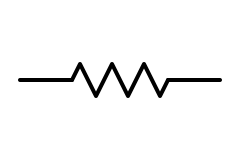
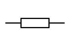
Limits current and drops voltage in proportion to the current through it (Ohm’s law). The most common part on any schematic.
The zigzag is the US form; IEC 60617 draws a plain rectangle. IEEE 315 also allows the rectangle, so US schematics drawn in modern CAD tools sometimes use it too. Either way the value goes beside the symbol, often in RKM code: 4k7 means 4.7 kΩ.
Also called: fixed resistor, resistance, zigzag, rectangle resistor
Variable resistor (rheostat)
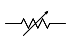
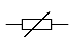
A two-terminal resistor whose value can be changed, used to set a current or trim a circuit.
An arrow drawn through any symbol means “adjustable” in both standards; only the resistor body changes. A preset trimmer is often drawn with a short bar (a T) instead of an arrowhead.
Also called: rheostat, adjustable resistor, trimmer
Potentiometer
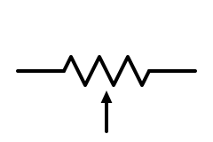
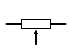
A resistor with a third, sliding terminal (the wiper), drawn as an arrow pointing at the body. Volume controls, setpoint knobs and sensor trims.
Same arrow-to-body convention in both standards. With the wiper tied to one end, a potentiometer becomes a rheostat.
Also called: pot, trimpot, wiper, voltage divider
Thermistor (NTC or PTC)
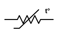
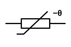
A resistor whose value changes strongly with temperature. NTC types fall as they warm (temperature sensing, inrush limiting); PTC types rise (resettable fuses, motor winding protection).
Both standards add a slanted line with a short foot, meaning the value varies non-linearly with a physical quantity. IEEE 315 marks it t°; IEC uses θ (or t°), with −θ for NTC and +θ for PTC.
Also called: NTC, PTC, temperature sensor, thermal resistor, inrush limiter
Photoresistor (LDR)
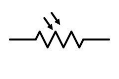
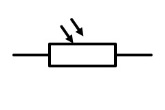
A resistor whose resistance drops in light. Dusk-to-dawn photocontrols on outdoor lighting and simple light sensors.
Arrows pointing in mean “responds to light” in both standards; arrows pointing out mean “emits light”, as on an LED.
Also called: LDR, light-dependent resistor, photocell, CdS cell, photoconductive cell
Capacitor
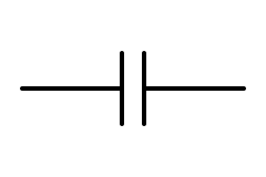
Two plates separated by an insulator: stores charge, blocks DC and passes AC. Decoupling, filtering, timing, motor starting and power-factor correction.
Two equal straight plates in both standards. IEEE 315 also has a style with one curved plate, still common on older US drawings, where the curve marks the outer foil or the negative side.
Also called: cap, condenser, non-polarized capacitor, ceramic capacitor, film capacitor
Polarized (electrolytic) capacitor
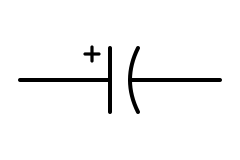
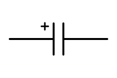
A capacitor that must be connected the right way round, such as aluminium electrolytic and tantalum parts. Power-supply smoothing and bulk energy storage.
The + mark is what matters. US schematics usually draw the negative plate curved; IEC uses two straight plates with a + beside the positive one. Old German drawings showed the plates as an open and a filled rectangle.
Also called: electrolytic capacitor, e-cap, tantalum capacitor, polarised capacitor, bulk capacitor
Variable capacitor
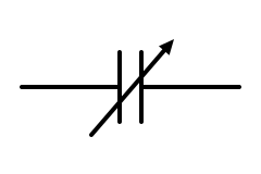
A capacitor whose value is set by turning a shaft or trimmer screw, for tuning radio circuits and trimming oscillators.
Same in both: the adjustable arrow through the plates. A varicap (varactor) is a different part: a diode used as a voltage-controlled capacitor.
Also called: tuning capacitor, trimmer capacitor, air-variable capacitor
Inductor (air core)
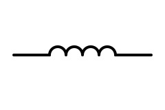
A coil of wire that stores energy in its magnetic field and opposes changes in current. Filters, chokes and switching converters.
Both standards draw a row of half-circles; four is usual, and the count means nothing. Hand-drawn US schematics often use looped curls instead.
Also called: coil, choke, winding, reactor
Iron-core inductor
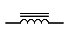
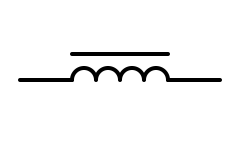
An inductor wound on a magnetic core for far more inductance per turn: line reactors, ballasts and mains chokes.
A straight line beside the winding means a magnetic core. US drawings often use two lines; IEC uses one. Many US drawings use dashed lines for a ferrite or powdered-iron core.
Also called: choke, reactor, line reactor, ferrite-core inductor, magnetic-core inductor
Transformer
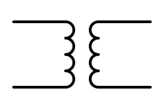
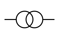
Two or more windings coupled by a shared magnetic field: steps AC voltage up or down and isolates circuits. Control transformers, power supplies and utility services.
US schematics draw two facing windings. IEC drawings, especially single-line diagrams, draw two overlapping circles, one per winding; IEC also has a winding form for detailed diagrams.
Also called: XFMR, xformer, TX, trafo, isolation transformer
Iron-core transformer
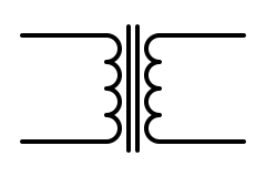
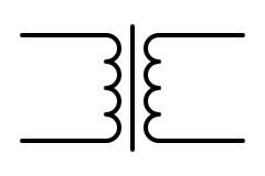
The everyday power transformer: windings on a laminated steel core. Control-circuit transformers (480 V to 120 V), doorbell and HVAC transformers, wall adapters.
The core is drawn between the windings: two lines on most US drawings, one line in the IEC winding form. IEC single-line diagrams usually use the two-circle form and leave the core out.
Also called: power transformer, control transformer, mains transformer, laminated-core transformer
Crystal (quartz)
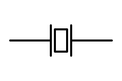
A slice of quartz between two electrodes that resonates at a precise frequency: the clock source for microcontrollers, radios and real-time clocks.
Same in both standards. Ceramic resonators use a similar symbol, often with a third (ground) terminal.
Also called: XTAL, quartz crystal, crystal oscillator, resonator, piezoelectric crystal
Fuse
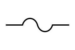
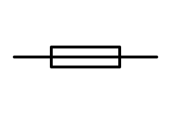
A conductor designed to melt and open the circuit on overcurrent. Branch-circuit, equipment and control-circuit protection.
The S-curve is the traditional US symbol. IEC draws a rectangle with the conductor running straight through it, which keeps it distinct from a resistor; IEEE 315 accepts that form too.
Also called: cartridge fuse, fusible link, fuse link, blade fuse
Varistor (MOV)
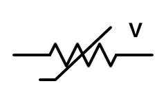
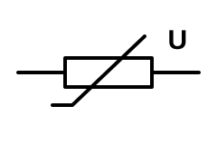
A resistor whose resistance collapses above a threshold voltage, clamping surges. Inside surge protective devices and across relay coils, contactors and power inputs.
Both standards use the resistor with the non-linear line, marked with the quantity it responds to: V on US drawings, U (the IEC letter for voltage) on IEC drawings.
Also called: MOV, metal-oxide varistor, VDR, voltage-dependent resistor, surge suppressor
Semiconductors and ICs (19)
Diodes, transistors, thyristors, optocouplers and amplifiers.
Diode
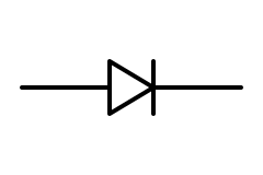
Lets current flow one way only, from anode (triangle) to cathode (bar). Rectifiers, reverse-polarity protection, flyback diodes across relay coils.
Same in both standards. The triangle may be filled or open; the bar matches the band printed on the part. The triangle points the way conventional current flows.
Also called: rectifier diode, rectifier, PN junction, signal diode
LED
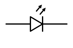
A diode that emits light when forward-biased; the arrows point away to show light leaving. Indicators, lighting and optocouplers.
Same in both standards. An LED needs a series resistor or a constant-current driver to set its current.
Also called: light-emitting diode, indicator, diode light
Photodiode
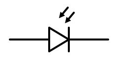
A diode that passes current in proportion to the light falling on it; the arrows point in. Light meters, optical receivers and smoke detectors.
Same in both. Do not confuse it with an LED: the arrow direction is the only difference.
Also called: light sensor, photo sensor, PIN photodiode
Zener diode
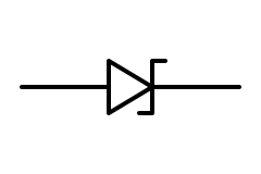
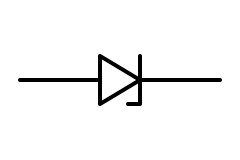
A diode built to conduct in reverse at a set breakdown voltage: a simple voltage reference, clamp or regulator.
US drawings usually bend both ends of the bar into a Z (IEEE 315 also allows a single bent end); IEC uses one short stroke at one end. Write the voltage beside it, such as 5V1 for 5.1 V.
Also called: Zener, breakdown diode, voltage reference diode, avalanche diode
Schottky diode
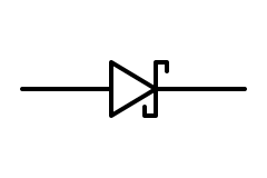
A fast diode with a low forward voltage (roughly 0.2 to 0.5 V). Switching power supplies, solar bypass diodes and battery OR-ing.
Same in both: the bar ends in small S-shaped hooks.
Also called: Schottky barrier diode, hot-carrier diode, SBD
TVS diode (bidirectional)
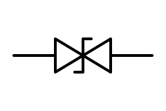
A diode built to absorb fast voltage spikes; the bidirectional type clamps both polarities. Protects data lines, DC inputs and control wiring.
Same in both: two breakdown diodes back to back sharing a Z-shaped bar. A unidirectional TVS uses the Zener symbol.
Also called: transient voltage suppressor, ESD diode, surge diode, bidirectional breakdown diode
Bridge rectifier
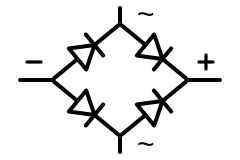
Four diodes arranged so that AC in gives DC out on both half-cycles. Power supplies, battery chargers and DC coil supplies.
Same in both. Block diagrams often shrink it to a square split by a diagonal, with ~ on the input side and = on the output side.
Also called: diode bridge, full-wave bridge, rectifier bridge, Graetz bridge
NPN transistor
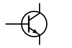
A bipolar transistor switched on by current into the base; the emitter arrow points out. Small-signal amplifiers, relay and LED drivers.
Same in both standards; the circle (envelope) is optional in both. Memory aid: NPN, “not pointing in”.
Also called: BJT, bipolar junction transistor, NPN
PNP transistor
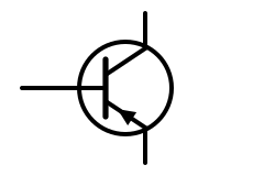
The complementary bipolar transistor: the emitter arrow points in, and it turns on when the base is pulled below the emitter. High-side switches and push-pull stages.
Same in both. In real circuits a PNP is usually drawn with the emitter at the top, toward the positive rail.
Also called: BJT, bipolar junction transistor, PNP
N-channel MOSFET (enhancement)
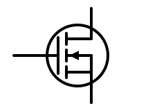
A voltage-controlled switch: a positive gate-to-source voltage turns it on. The broken channel line means enhancement mode, off at zero gate voltage.
Same in both. The arrow on the body connection points in for N-channel. Datasheets usually add the built-in body diode between drain and source.
Also called: NMOS, power MOSFET, logic-level MOSFET, N-MOSFET, IGFET
P-channel MOSFET (enhancement)
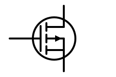
Turns on when the gate is pulled below the source. Common as a high-side switch and for reverse-polarity protection.
Same in both. The body arrow points out for P-channel.
Also called: PMOS, P-MOSFET, IGFET
JFET (N-channel)
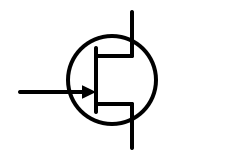
A junction FET that conducts with zero gate voltage and is pinched off by a negative gate. Low-noise amplifiers and analog switches.
Same in both. The solid channel line marks a depletion device; the gate arrow points in for N-channel and out for P-channel.
Also called: junction FET, N-JFET, depletion-mode FET
IGBT
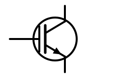
An insulated-gate bipolar transistor: a MOSFET-style gate driving a bipolar output. The main switch in VFDs, inverters, welders, induction heaters and EV drives.
Same in both: an insulated gate like a MOSFET, with a collector and an arrowed emitter like a BJT.
Also called: insulated-gate bipolar transistor, power switch
SCR (thyristor)
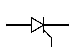
A diode that stays off until a gate pulse turns it on, then latches until the current falls to zero. Controlled rectifiers, soft starters and crowbar circuits.
Same in both; the gate lead leaves from the cathode side.
Also called: thyristor, silicon-controlled rectifier
Triac
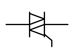
An AC switch: two thyristors in inverse parallel sharing one gate. Light dimmers, fan speed controls and solid-state relays.
Same in both. The terminals are MT1, MT2 and the gate; the gate is referenced to MT1.
Also called: bidirectional thyristor, TRIAC, AC switch
Diac
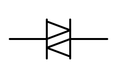
A two-terminal trigger device that conducts in either direction once the voltage passes its breakover point (around 30 V). It fires the triac in a dimmer.
Same in both: a triac with no gate.
Also called: DIAC, trigger diode, bidirectional trigger diode
Optocoupler
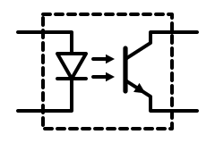
An LED and a phototransistor in one package: it passes a signal by light while keeping the two sides electrically isolated. Power-supply feedback, PLC inputs, isolated interfaces.
Same in both; the box marks a single package. The output side varies: phototransistor, photo-triac or logic gate.
Also called: opto-isolator, photocoupler, optoisolator, opto
Operational amplifier
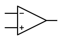
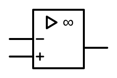
A high-gain differential amplifier with inverting (−) and non-inverting (+) inputs. With feedback it amplifies, filters, buffers, sums and integrates.
US practice is the triangle. IEC 60617 draws a rectangle with a small triangle and ∞ (very high gain) inside, though many European schematics also use the triangle.
Also called: op amp, opamp, operational amplifier, amplifier
Comparator
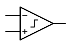
Compares two voltages and drives its output high or low depending on which is larger. Battery monitors, thermostats, zero-cross detectors and window comparators.
Drawn as an amplifier triangle, exactly like an op-amp; the part number, a COMP label or a small step mark inside (as here) tells them apart. Many comparators have an open-collector output that needs a pull-up resistor.
Also called: voltage comparator, comparator IC, LM393
Logic gates (7)
The US distinctive shapes beside the IEC rectangular forms with their qualifying marks.
AND gate
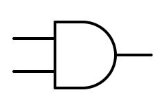
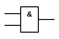
Output is 1 only when every input is 1. Interlocks: run only if the guard is closed and the start is pressed.
IEC 60617-12 uses a rectangle marked & (“and”). IEEE 91 brought the IEC rectangular forms into the US standard, but the older curved shapes still dominate US textbooks, schematics and datasheet diagrams.
Also called: AND, logical AND, conjunction
OR gate
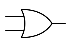
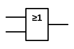
Output is 1 when at least one input is 1. Any of several stop or alarm conditions.
IEC writes ≥1: the output is true when one or more inputs are true.
Also called: OR, logical OR, disjunction
NOT gate (inverter)
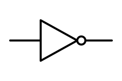
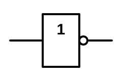
Output is the opposite of the input. Turns active-low signals into active-high ones.
The small circle means inversion in both styles. IEC marks the box 1 (a buffer) and puts the circle on the output.
Also called: inverter, NOT, negation
NAND gate
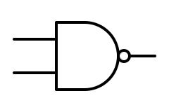
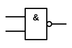
An AND gate with an inverted output: 0 only when every input is 1. Any logic function can be built from NAND gates alone.
Both styles add the inversion circle to the AND symbol.
Also called: NAND, not-AND, universal gate
NOR gate
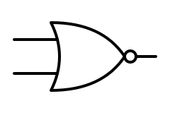
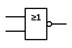
An OR gate with an inverted output: 1 only when every input is 0. Also a universal gate.
Both styles add the inversion circle to the OR symbol.
Also called: NOR, not-OR
XOR gate
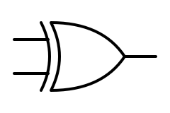
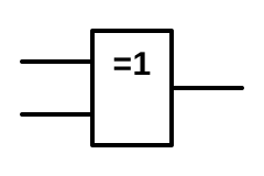
Output is 1 when the inputs differ. Parity checks, adders and two-way (three-way US) switching logic.
US adds a second curved line at the inputs. IEC writes =1: exactly one input must be true.
Also called: exclusive OR, EOR, EXOR
XNOR gate
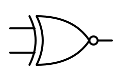
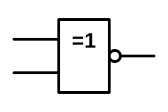
Output is 1 when the inputs are equal. Equality comparators.
An XOR with an inverted output. For two inputs some IEC drawings mark the box = (logic identity) instead.
Also called: exclusive NOR, equivalence gate, ENOR, EXNOR
Sources and grounds (10)
Ideal sources, cells and batteries, and the four kinds of ground.
DC voltage source
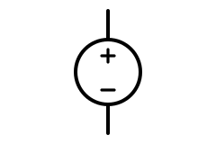
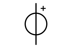
An ideal source that holds a fixed voltage whatever current is drawn. Circuit-analysis and simulation diagrams use it for supplies.
US textbooks mark + and − inside the circle. IEC 60617 draws the conductor straight through the circle (an ideal source has zero internal resistance) and marks polarity outside. Real supplies are often drawn as a battery.
Also called: ideal voltage source, DC supply, independent voltage source, VDC
AC voltage source
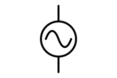
A sinusoidal voltage source: the mains supply, a utility feed or a signal generator in a schematic.
Same in both; IEC may write the AC sign ~ inside the circle. Write the voltage and frequency beside it (120 V 60 Hz, 230 V 50 Hz).
Also called: AC source, sine source, AC supply, signal generator, VAC
Current source
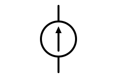
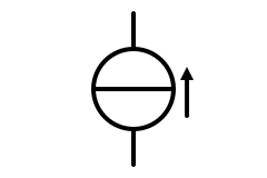
An ideal source that forces a fixed current whatever the voltage. Models transistor outputs, LED drivers and 4–20 mA sensor loops.
US: a circle with an arrow inside showing the current direction. IEC 60617: a circle crossed by a line at right angles to the conductor (infinite internal resistance), with the direction marked outside.
Also called: ideal current source, constant-current source, independent current source
Battery
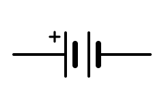
Two or more cells in series. The long thin plate is positive and the short thick plate negative.
Same in both. The drawing need not show the real number of cells: write the voltage beside it (12 V). A dashed line between two cells also means “more cells here”.
Also called: battery pack, cells, accumulator, DC source
Cell
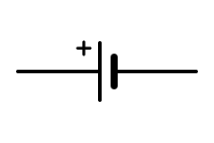
A single electrochemical cell, such as a 1.5 V alkaline, a 3 V lithium coin cell or a 3.6 V lithium-ion cell.
Same in both: long line positive, short line negative.
Also called: single cell, coin cell, button cell, primary cell
Solar cell (PV)
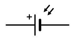
A cell that produces current from light. PV modules are many cells in series; PV system drawings usually show a module or array as a box with the cell symbol.
Same in both: a cell with incoming light arrows.
Also called: photovoltaic cell, PV cell, solar panel, PV module
Earth ground
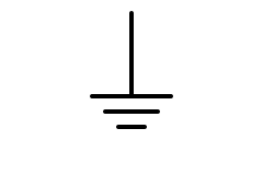
A connection to the earth itself, through a ground rod or the grounding electrode system. On power drawings it marks the grounding electrode connection.
Same in both (IEC: earth, general symbol). Electronics schematics often use it loosely for circuit common; save it for real earth connections.
Also called: ground, earth, grounding electrode, GND
Chassis ground
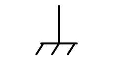
A connection to the metal frame or enclosure of the equipment, which may or may not be connected to earth.
Same in both (IEC: frame or chassis).
Also called: frame ground, chassis, frame, case ground
Signal ground
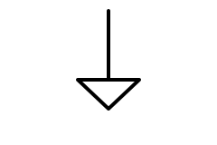
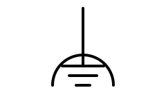
The reference point for signal voltages in electronics, often kept separate from noisy power returns and the safety ground until a single point.
The hollow triangle is IEEE 315’s signal (low-noise) ground. IEC has no triangle; its nearest symbol is functional (noiseless) earth, the earth sign under an arc, and many IEC schematics just label the net 0 V.
Also called: signal common, analog ground, AGND, 0 V, reference ground, common
Protective earth
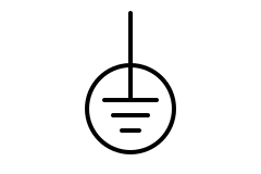
The safety earth connection that carries fault current and keeps exposed metal at earth potential. Marks the PE terminal on equipment and in panels.
Same in both: the earth sign in a circle (IEC 60417-5019), also used on US equipment. In US wiring terms this is the equipment grounding conductor.
Also called: PE, protective ground, safety ground, equipment grounding conductor, EGC, earth terminal
Switching and protection (14)
Switches, push buttons, relay and contactor contacts, breakers, overloads and residual-current devices.
SPST switch
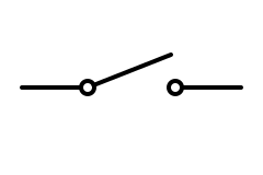
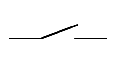
Opens or closes one circuit: single pole, single throw. Light switches, power switches.
US drawings put small open circles at the terminals. IEC draws the moving contact as a slanted line from the conductor, with no circles.
Also called: on-off switch, single-pole single-throw, toggle switch, make contact, single-pole switch
SPDT switch
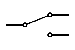
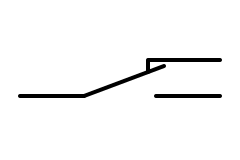
One common terminal connects to either of two others. Selector switches; in house wiring, the US three-way switch is an SPDT.
IEC draws the normally closed side as a hooked contact that the blade rests on. Watch the naming trap: a US “three-way” switch is a UK “two-way” switch.
Also called: changeover switch, single-pole double-throw, two-way switch, three-way switch, transfer contact, form C
DPDT switch
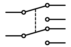
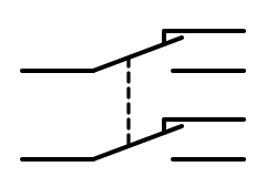
Two SPDT switches operated together. Motor reversing, polarity swapping and switching two lines at once.
The dashed line means “operated together” in both standards.
Also called: double-pole double-throw, reversing switch, two-pole changeover
Push button (normally open)
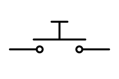
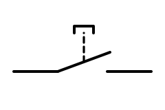
Closes only while pressed. The start button in a motor control circuit, a doorbell push.
US: a bridging bar above two terminals, with a stem to push it down. IEC: a make contact with a dashed link to the push actuator.
Also called: push-to-make, momentary switch, NO push button, start button, pushbutton
Push button (normally closed)
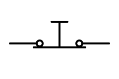
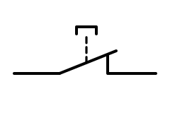
Opens only while pressed. The stop button in a three-wire motor control circuit, emergency stops (with a latching head).
US: the bar sits under the terminals, touching them. IEC: a break contact with the push actuator.
Also called: push-to-break, NC push button, stop button, momentary NC
Limit switch (normally open)
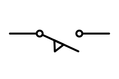
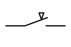
A switch worked by machine motion, such as a door, cam or moving carriage, to confirm a position or stop travel.
Both mark the actuator with a small wedge on the moving contact: IEEE 315 hangs the open blade below the terminals with the wedge underneath; IEC draws a make contact with a small triangle touching the blade.
Also called: position switch, travel switch, LS, end switch, micro switch
Relay or contactor coil
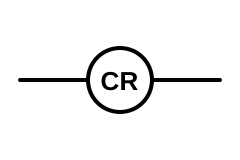
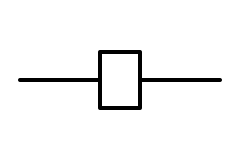
The electromagnet that operates a relay’s or contactor’s contacts. Its label (CR1, K1, M) ties it to its contacts elsewhere on the drawing.
US ladder diagrams draw the coil as a circle with its tag inside. IEC uses a rectangle, and so does IEEE 315 itself; electronic schematics often draw a box or an inductor next to the contacts.
Also called: coil, operating coil, solenoid, control relay, CR, K
Normally open contact
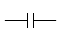
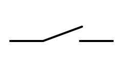
A relay contact that closes when its coil is energized. Contacts are always drawn in the de-energized (shelf) state.
US ladder: two parallel lines. IEC: the make contact, the same symbol as a switch.
Also called: NO contact, make contact, form A, normally open
Normally closed contact
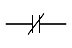
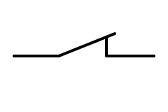
A relay contact that opens when its coil is energized.
US ladder: the parallel lines with a diagonal slash. IEC: the break contact with its hooked fixed contact.
Also called: NC contact, break contact, form B, normally closed
Contactor (main contact)
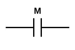
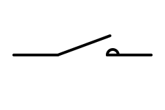
A heavy-duty relay that switches motor and power circuits; its main contacts carry the load current and its coil sits in the control circuit.
US drawings use the same contact as a relay, tagged M for a motor starter. IEC adds a small half-circle to the fixed contact: the contactor function mark.
Also called: magnetic contactor, motor starter, main contact, power contact
Circuit breaker
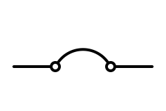
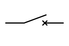
An automatic switch that opens on overcurrent and can be reset. Panelboard breakers, MCBs, molded-case and power breakers.
US: an arc bridging two terminals (IEEE 315); US single-line diagrams also draw power breakers as a small square. IEC: a switch with a cross on the fixed contact.
Also called: breaker, CB, MCB, MCCB, molded-case circuit breaker
Thermal overload
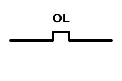
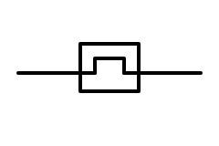
Senses motor current by heating and opens its control contact if the motor stays overloaded too long. Part of every motor starter.
IEEE 315 draws the thermal element as a stepped line in the conductor, and IEC puts the same step inside a rectangle. US motor-control drawings tag the heaters and their normally closed contact OL.
Also called: overload relay, OL, overload heater, bimetal overload, thermal relay
Disconnect switch
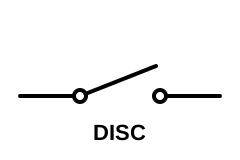
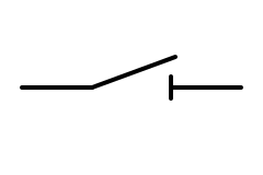
A manual switch that isolates equipment for maintenance. Unless it is rated for load break, open it only after the load is off.
US drawings use the knife-switch blade and label it. IEC adds a short bar across the fixed contact for a disconnector (isolator).
Also called: disconnect, isolator, isolating switch, safety switch, disconnector, switch-disconnector
RCD / GFCI
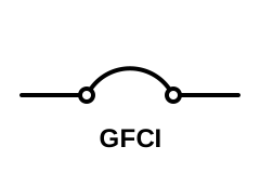
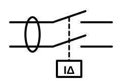
Trips when the current going out on the line conductor does not all come back on the neutral, because some is leaking to earth, possibly through a person. Personnel protection trips at 4–6 mA (US Class A GFCI) or 30 mA (IEC RCD).
US drawings have no special GFCI symbol in everyday use: they label a breaker or receptacle GFCI (or GFI). IEC drawings show the contacts linked to a residual-current release marked IΔ, with both conductors passing through a sensing core.
Also called: GFCI, GFI, RCD, RCCB, RCBO, ground-fault circuit interrupter, residual current device, earth leakage breaker, ELCB
Machines and loads (8)
Motors, generators, lamps, heaters and sounders.
Motor
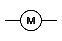
A circle with M. On power drawings it sits at the end of the branch circuit with its horsepower or kilowatts and full-load current beside it.
Same in both. IEC adds the supply: M 3~ for a three-phase motor; US drawings often write the horsepower inside or beside the circle instead.
Also called: electric motor, induction motor, MTR, M
Generator
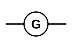
Standby and prime-power generators on single-line diagrams, alternators on engines and turbines.
Same in both; G 3~ for a three-phase alternator.
Also called: GEN, alternator, genset, standby generator
Lamp
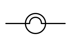
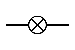
A lamp or indicator light. On control panels a pilot light usually carries a colour letter (R red, G green, A amber).
This is the classic US/IEC difference: IEC (and UK and European practice) draws a circle with a cross; US drawings show a filament inside the circle, and US ladder diagrams draw pilot lights as a circle with short light rays.
Also called: light, bulb, pilot light, indicator lamp, signal lamp, light fixture
Heater (heating element)
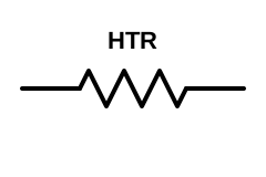
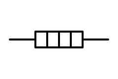
A resistive element built to make heat: baseboard heaters, water-heater elements, enclosure and anti-condensation heaters.
US drawings use a resistor tagged HTR. IEC 60617 has its own heating-element symbol: a rectangle divided into cells.
Also called: heating element, resistance heater, space heater, element, HTR
Buzzer
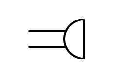
Makes a tone or buzz when energized: alarm panels, appliance beepers, warning sounders.
The leads go into the curved side; on a bell they go into the flat side. Building plans and fire-alarm drawings use their own signalling symbols, so check the legend.
Also called: sounder, beeper, piezo buzzer, piezo sounder
Bell
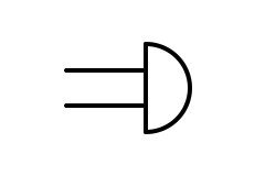
An electromechanical bell: fire-alarm bells, doorbells, school and factory signals.
Same in both: a dome with the leads going into its flat side (a buzzer reverses it). A gong adds a line across the dome.
Also called: alarm bell, doorbell, chime, gong
Loudspeaker
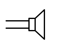
Turns an electrical audio signal into sound: PA systems, voice evacuation, intercoms.
Same in both: a small rectangle (the magnet) with a flared cone.
Also called: speaker, loudspeaker, horn, PA speaker
Antenna
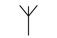
Radiates or receives radio signals: Wi-Fi, cellular, GPS, two-way radio and broadcast reception.
Same in both. “Aerial” is the British word.
Also called: aerial, ANT, antenna
Meters (5)
Indicating instruments: a circle with the measured quantity inside.
Voltmeter
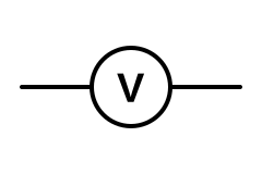
Measures voltage; connected in parallel, across the part being measured.
Same in both: a circle with the unit symbol. IEC uses a square for recording instruments and a rectangle for integrating meters such as kWh.
Also called: voltage meter, V
Ammeter
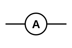
Measures current; connected in series, or through a current transformer on power circuits.
Same in both. Clamp meters measure current without breaking the circuit, but the diagram symbol is the same.
Also called: amp meter, ammeter, A
Wattmeter
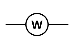
Measures real power. It has a current circuit in series and a voltage circuit in parallel.
Same in both. Detailed drawings show the current and voltage coils separately.
Also called: power meter, W
Ohmmeter
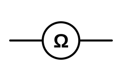
Measures resistance with its own internal source, so it is used only on de-energized circuits.
Same in both. An insulation-resistance tester (megger) is often marked MΩ.
Also called: resistance meter, megohmmeter, insulation tester, Ω
Oscilloscope
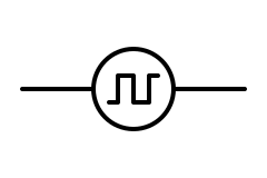
Displays voltage against time. Shown on test set-ups and lab diagrams.
Same in both: an instrument circle with a waveform inside.
Also called: scope, CRO, DSO
Building plan symbols (US practice) (16)
Common US floor-plan symbols. Offices vary, so the legend on the drawing set always wins.
Duplex receptacle
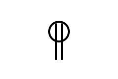
A standard two-outlet wall receptacle (NEMA 5-15R or 5-20R). Mounting height and circuit number are often written beside it.
One line through the circle is a single receptacle, three a triplex. IEC and UK plans draw a socket outlet as a half-circle instead.
Also called: duplex outlet, outlet, wall plug, convenience outlet, power point, socket outlet
GFCI receptacle
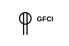
A duplex receptacle with built-in ground-fault protection, required by NEC 210.8 in bathrooms, kitchens, garages, outdoors and the other locations it lists.
Usually the duplex symbol tagged GFCI or GFI; some offices fill the circle instead. WP is added for a weatherproof cover outdoors.
Also called: GFI outlet, GFCI outlet, ground-fault receptacle
240 V receptacle
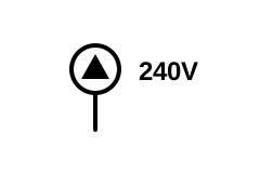
A dedicated receptacle for a 240 V appliance: range, dryer, welder or EV charger.
Usually the special-purpose receptacle: a circle with a filled triangle. Practice varies (some offices use letters such as R for range or D for dryer), and good drawings write the NEMA configuration, such as 14-50R or 6-50R, beside it.
Also called: dryer outlet, range outlet, special-purpose receptacle, 240 volt outlet, 14-50R, 6-50R
Switch (single-pole)
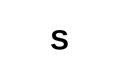
A single-pole wall switch. A dashed arc on the plan links it to the lights it controls.
Subscripts tell the type: S3 three-way, S4 four-way, SD or SDM dimmer, SP switch with pilot light, SWP weatherproof, SK key-operated.
Also called: light switch, wall switch, S
Three-way switch
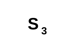
One of a pair of switches that control the same lights from two places, such as the top and bottom of a stair.
Electrically it is an SPDT switch. In UK terms this is a two-way switch.
Also called: 3-way switch, S3, two-way switch (UK)
Four-way switch
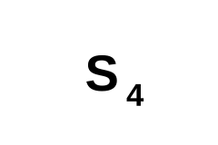
Goes between two three-way switches so the same lights can be controlled from three or more places.
Electrically it is a crossover (DPDT wired as a reverser). In UK terms this is an intermediate switch.
Also called: 4-way switch, S4, intermediate switch (UK)
Dimmer switch
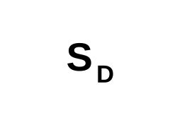
A wall control that varies light output. Its type (incandescent, LED/CFL, 0–10 V) belongs in the fixture or device schedule.
Most legends write S with a D subscript; others use SDM or DIM. Check the legend, because on some older drawings the same letters meant a door switch.
Also called: dimmer, SD, SDM, DIM, S sub D
Ceiling light
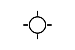
A surface-mounted ceiling lighting outlet or fixture. A letter inside or beside it keys it to the fixture schedule.
A plain circle is the traditional ceiling outlet; many offices add short rays or a letter. IEC and UK plans draw a light as a circle with a cross.
Also called: ceiling fixture, light outlet, ceiling outlet, luminaire
Wall light
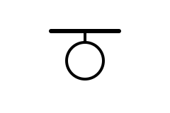
A wall-mounted lighting outlet or sconce, drawn with a short stem to the wall line.
The heavy line here stands for the wall. Exterior wall packs are tagged in the fixture schedule.
Also called: wall sconce, bracket light, wall fixture, wall outlet
Recessed light
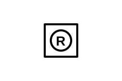
A recessed downlight (can light) set into the ceiling. Fixture type and trim come from the fixture schedule.
Often drawn to scale: a small circle (or a circle in a square) for a downlight, a rectangle for a recessed troffer.
Also called: can light, downlight, pot light, recessed can, high hat
Ceiling fan
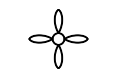
A ceiling fan or fan-light outlet. The box above it must be listed to support a fan, not just a light fixture.
Blades around a small circle; a fan with a light kit may combine this with the light symbol.
Also called: fan, paddle fan, ceiling fan outlet
Smoke detector
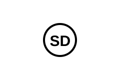
A smoke alarm or detector. Dwelling alarms are interconnected so one sounding sets off all of them.
Fire-alarm drawings use their own legend (NFPA 170 symbols); residential plans usually just circle SD, with CO for carbon monoxide.
Also called: smoke alarm, SD, smoke detector, CO/smoke alarm
Junction box
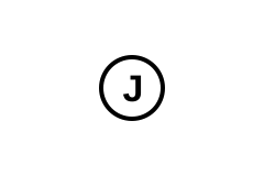
An outlet box used only for splices or a future connection, with a blank cover.
Drawn as J in a circle or in a small square. The NEC requires junction boxes to stay accessible, so one is never buried in a wall or ceiling.
Also called: J-box, junction box, splice box, pull box
Panelboard
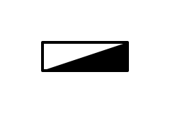
A lighting or power panel; its tag (LP-1, PP-2, Panel A) matches the panel schedule.
Drawn as a long rectangle against the wall, partly or fully filled or hatched. What the fill means (flush or surface mounting, lighting or power panel) varies by office, so check the legend.
Also called: panel, electrical panel, breaker panel, load center, distribution board, consumer unit
Electric meter
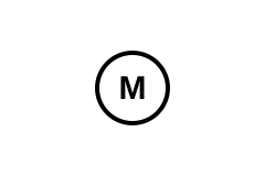
The utility revenue meter (meter socket), usually on an exterior wall next to the service equipment.
Some offices use a circle with M, others a circle or rectangle with kWh. Tag it if there are several meters.
Also called: meter, meter base, meter socket, kWh meter, utility meter
Home run
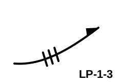
The run from the last outlet back to the panel. The arrow points to the panel, and the tag names the panel and circuit (LP-1-3: panel LP-1, circuit 3).
Conventions vary by office: hash marks usually count the conductors (often only when there are more than two), some legends use one arrowhead per circuit, and marks for neutral and ground differ. Read the legend.
Also called: home run arrow, circuit to panel, HR
No symbol matches that search. Try a shorter word, another name (pot, GFI, contactor) or a designator such as R or K.
Every drawing has an SVG link: black lines on a transparent background at twice the size shown, ready for Inkscape, draw.io, Visio, a CAD import or a word-processor document. The whole chart is also a single file you can print as a wall chart or keep on a tablet: download the full symbols chart (SVG).
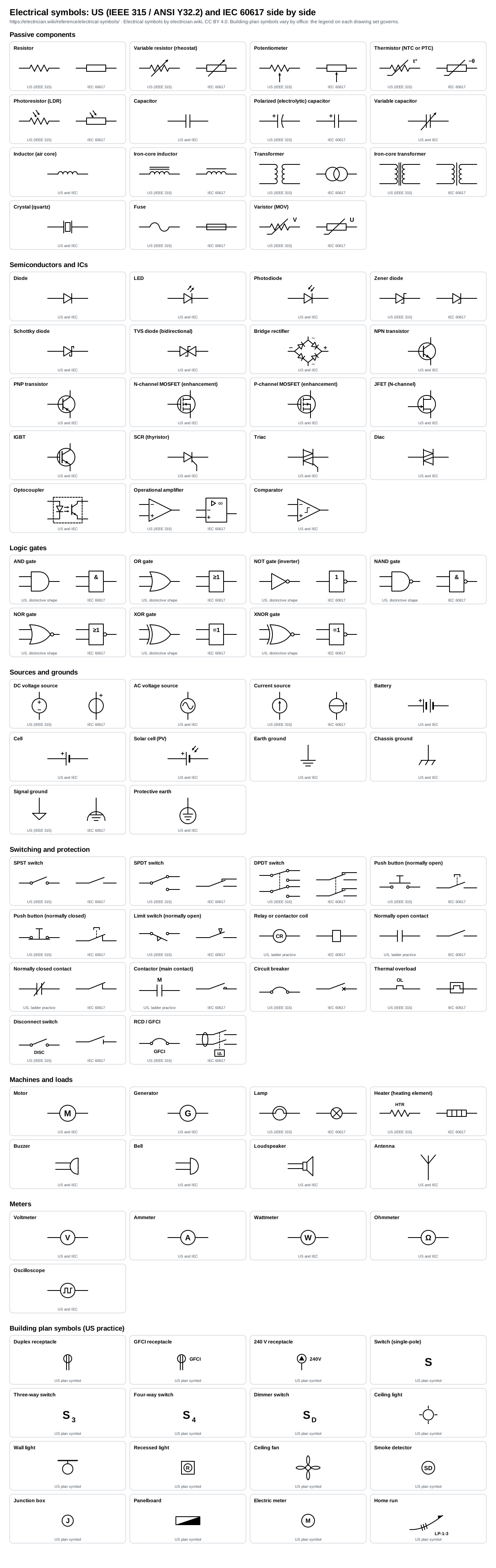
Schematics, one-line diagrams and building plans
Electrical drawings come in three main kinds, and the same symbol can carry a slightly different weight in each. Knowing which kind you are holding tells you what a line on the page actually represents.
A schematic shows how parts connect electrically. Every conductor gets its own line, and nothing on the page says where a part physically sits. Electronics schematics, control wiring diagrams and the ladder diagrams used for motor control are all schematics. They are drawn with everything de-energized and at rest, and the designator beside each symbol (R1, K2, PB3) ties it to the parts list.
A one-line diagram, also called a single-line diagram, shows a power system with one line standing for all the conductors of a circuit, whether that is two wires or three phases and a neutral. It answers what feeds what, at what voltage and through which protective device, with the ratings written beside the symbols: transformer kVA and impedance, breaker frame and trip rating, conductor sizes. Utilities, inspectors and anyone doing a fault-current or arc-flash study start here.
A building plan places devices where they go: receptacles along the walls, switches beside the doors, fixtures on the ceiling. It shows which switch controls which light and which panel circuit each run belongs to, but not how the conductors are spliced. The installer works that out from the plan, the panel schedule and the code.
Schematic
Every conductor gets its own line; nothing about where the parts are. The equipment ground is left out for clarity.
One-line diagram
One line stands for all the conductors. It shows what feeds what, through which protective device, at what rating.
Building plan
Where things go. The dashed line ties switch a to light a; the arrow is the home run back to panel LP-1, circuit 3.
Reading habits that work on all three:
- Start with the legend and the general notes. Plan symbols in particular are defined per drawing set, and an office’s legend overrides any chart, this one included.
- On a schematic, trace from the source: follow the supply through the protective devices and switches to each load, then back along the return.
- On a ladder diagram, the two vertical rails are the control supply. Each rung carries contacts on the left and one output, such as a coil or a pilot light, on the right; the numbers printed beside a coil list the rungs where its contacts appear.
- On a one-line diagram, read from the utility or generator downward and note each device’s rating as you pass it.
- On a plan, match every home-run tag (LP-1-3 means panel LP-1, circuit 3) to the panel schedule, and look for mounting heights, usually marked AFF for above finished floor.
The standards behind the symbols
IEEE 315 and ANSI Y32.2: US schematics
Most US schematic symbols come from IEEE Std 315-1975, Graphic Symbols for Electrical and Electronics Diagrams, which was also published as the American National Standard ANSI Y32.2-1975. It runs from resistors and contacts to semiconductors and includes the class letters used for reference designators. IEEE reaffirmed it in 1993, then on 7 November 2019 moved it to inactive-reserved status: it is no longer maintained, but it remains available, and no newer US standard took its place. A 1986 supplement, IEEE 315A, set symbols from IEC Publication 617 beside their IEEE counterparts and was retired at the same time.
Inactive is not the same as obsolete. IEEE 315 symbols are still the everyday language of US schematics, CAD libraries and trade training, and NFPA 79, the electrical standard for industrial machinery, still carries an informative figure of selected ANSI Y32.2/IEEE 315 symbols beside their IEC equivalents. That is the practical reason this chart labels US forms by IEEE 315 rather than by any newer document.
IEEE 91: logic gates
Logic symbols have their own standard, IEEE Std 91 (ANSI Y32.14), Graphic Symbols for Logic Functions, last revised with its 1991 supplement. Its 1973 edition brought the IEC’s rectangular symbols into the US standard, and the 1984 edition absorbed all of the IEC’s approved logic work, including the dependency notation used to describe complex chips. The older curved shapes are still what most US engineers learn first and what most US schematics use; chip datasheets often show both.
IEC 60617: the international database
IEC 60617, Graphical symbols for diagrams, is the standard used across Europe and most of the world, and national editions such as BS EN 60617 in the UK reproduced its parts. It is no longer a book. Since 2001 the IEC has maintained it as an online database: the printed parts were withdrawn between 2001 and 2004, and the BS EN editions have been withdrawn too. The database holds more than 1,500 symbols, each with its own identifier, and access is by annual subscription.
Symbols printed on equipment itself, such as the protective-earth sign beside a terminal, come from a separate database, IEC 60417. Its numbers appear on nameplates and in manuals: 5017 is earth, 5018 functional earthing, 5019 protective earth and 5020 frame or chassis.
US building plans: office practice
Plan symbols are the least standardized of the three. ANSI Y32.9-1972, Graphic Symbols for Electrical Wiring and Layout Diagrams Used in Architecture and Building Construction, set the classic forms (IEEE still lists it, last reaffirmed in 1989). The electrical contractors’ association publishes its own symbols standard, NECA 100, the US National CAD Standard includes a symbols library that many design offices use, and nearly every engineering firm keeps its own legend on top. The core is stable: circles with lines for receptacles, S with a subscript for switches, arrows for home runs. Details such as how a GFCI, a special-purpose outlet or a dimmer is marked change from one drawing set to the next, which is why this chart presents plan symbols as common practice.
Conventions beyond the shapes
The two systems also lay drawings out differently. US ladder diagrams run horizontal rungs between two vertical supply rails, with numbered rungs and wire numbers. European circuit diagrams usually run the current paths vertically between horizontal supply lines and identify devices with codes such as -K1 or -Q2 under IEC 81346, where the leading minus sign marks the product part of the designation. US control drawings use device abbreviations instead, listed in NFPA 79: CR for a control relay, M for a motor starter, OL for an overload relay, PB for a push button.
US or IEC? How to tell at a glance
Most symbols are drawn the same way everywhere. A handful are not, and those few let you identify a drawing’s convention in seconds:
| Symbol | US | IEC 60617 | The tell |
|---|---|---|---|
| ResistorZigzag against a plain rectangle | Zigzag against a plain rectangle | ||
| LampA filament loop in the circle against a cross | A filament loop in the circle against a cross | ||
| FuseAn S-curve against a rectangle with the line running through | An S-curve against a rectangle with the line running through | ||
| Normally open contactTwo parallel lines (US ladder) against a slanted blade | Two parallel lines (US ladder) against a slanted blade | ||
| Normally closed contactA slash through the lines against a blade resting on a hook | A slash through the lines against a blade resting on a hook | ||
| Circuit breakerAn arc over two terminals against a cross on the contact | An arc over two terminals against a cross on the contact | ||
| Relay or contactor coilA circle with its tag (US ladder) against a rectangle | A circle with its tag (US ladder) against a rectangle | ||
| Zener diodeA Z-shaped bar against a single stroke | A Z-shaped bar against a single stroke | ||
| Polarized (electrolytic) capacitorA curved negative plate against two straight plates and a + | A curved negative plate against two straight plates and a + | ||
| TransformerTwo facing windings against two overlapping circles | Two facing windings against two overlapping circles | ||
| AND gateA D-shaped body against a box marked & | A D-shaped body against a box marked & | ||
| Operational amplifierA triangle against a box marked with a small triangle and ∞ | A triangle against a box marked with a small triangle and ∞ |
- Zigzag resistors, open circles at switch terminals, contacts drawn as two parallel lines and coils drawn as circles: a US drawing, and a ladder diagram if the contacts look like that.
- Rectangles for resistors and coils, slanted contact blades carrying function marks (a cross for a breaker, a half-circle for a contactor, a bar for a disconnector) and a circle with a cross for every lamp: IEC.
- Device tags such as CR1, M, OL and 1PB are US; tags such as -K1, -Q1, -F2 and -S3 are IEC 81346.
- A decimal comma (4,7 kΩ) points to a European origin. Resistance codes such as 4k7, 2R2 and 10M are used everywhere, because a decimal point can vanish in a copy.
- Many modern drawings mix the two, especially ones built from CAD libraries. That is common and usually harmless; what matters is staying consistent within a drawing set and saying so in the legend.
Dots, crossings, polarity and normal states
Joined
Crossing, not joined
Four-way dot: avoid
Better: two offset Ts
Hop: not joined (older style)
Polarity dots
Connections. A filled dot where lines meet means they are joined. Lines that cross without a dot are not. Good practice avoids four-way junctions altogether: two offset T-junctions say the same thing and survive a poor print, where a faded dot would turn a junction into a crossing. Some older hand-drawn schematics worked the other way, treating a plain crossing as a connection and drawing a small hop where wires crossed without connecting, so on an old drawing check the legend before assuming either way.
Polarity. On cells and batteries the long plate is positive. On a diode the bar is the cathode, matching the band printed on the part. Polarized capacitors carry a + mark, and on US drawings a curved negative plate. Dots beside transformer windings mark the ends that swing positive together, which matters when you parallel transformers, wire a current transformer to a meter or relay, or connect two windings in series.
Normal states. Switches and contacts are drawn in their shelf state: unoperated, with coils de-energized and nothing pressing, heating or filling them. A normally closed contact is drawn closed even if, in normal running, its coil is energized and the contact is open. Pressure, level, temperature and flow switches are drawn as they rest with no process acting on them, so the note beside the symbol, such as “opens on rising pressure”, matters as much as the drawing.
Reference designators
The letters and numbers beside a symbol tie it to the parts list, to the markings on a circuit board and to every other place the same part appears on the drawing. US electronics practice descends from the class letters in IEEE 315 and is maintained today in ASME Y14.44 (2008, reaffirmed 2024). Industrial control drawings use the device abbreviations listed in NFPA 79 instead. The two sets disagree on a few letters, and that is where most mix-ups start.
| Letter | Usually means | Also seen, and where it differs |
|---|---|---|
| R | Resistor | RES on control drawings; POT or RV for a potentiometer, RT for a thermistor |
| C | Capacitor | CAP on control drawings |
| L | Inductor, choke | X for a reactor on control drawings |
| D | Diode, LED | CR on older US electronics drawings, where it meant crystal rectifier |
| Q | Transistor, thyristor | SCR on control drawings |
| U | Integrated circuit, module | IC on control drawings |
| K | Relay, contactor | CR (control relay), CON (contactor) and M (motor starter) on control drawings |
| F | Fuse | FU on control drawings |
| S | Switch | PB push button, LS limit switch, SS selector switch |
| M | Motor | On control drawings M is the motor starter and the motor itself is MTR |
| T | Transformer | CT for a current transformer |
| DS | Indicator lamp or display | LT (pilot light) on control drawings |
| J, P | Connector: J the fixed jack, P the mating plug | PL also means plug on control drawings |
| Y | Crystal, resonator | XTAL |
| BT | Battery | B |
European drawings follow IEC 81346-2, which assigns letters by what a device does rather than what it is: switching devices such as contactors and circuit breakers come under Q, relays under K and motors under M. The same contactor can therefore be K1 on a US electronics schematic, M on a US motor-control drawing and -Q1 on a European one, while its symbol barely changes.
Common mistakes
- Reading a crossing as a connection, or the reverse. Look for the dot, and never draw four wires into one.
- Reading contacts in their operated state. A drawing shows every contact at rest; on a running machine, many of them have changed state.
- Confusing look-alikes. An LED and a photodiode differ only in the direction of the arrows, a Zener and a Schottky only in the ends of the bar, an NPN and a PNP only in the direction of the emitter arrow.
- Fitting a polarized part backwards. The curved plate on a US capacitor symbol is the negative side, and the long plate of a cell is positive.
- Trusting letters across disciplines. LS is a loudspeaker on an electronics schematic and a limit switch on a control drawing; CR is a diode on old electronics drawings and a control relay in a panel; M is the motor on an electronics schematic but the motor starter on a control drawing, where the motor is MTR.
- Treating plan symbols as universal. A filled circle can mean GFCI in one office and something else entirely in the next, and a switch subscript can mean dimmer on one job and door switch on another. Read the legend.
- Using the earth symbol for every return. Earth, chassis, signal ground and protective earth are different connections. A drawing that blurs them invites noise problems and, worse, a missing safety ground.
- Mistranslating switch names. A US three-way switch is a UK two-way switch, and a US four-way switch is a UK intermediate switch.
Once the symbols make sense, put numbers to them. Our electrical calculators work out resistor values, power and transformer sizing, including an LED resistor calculator, and you can build and test a circuit in the online simulator before you wire it. Connector pin numbering is on the pinout pages, conductor colours by country are in the wire colour code chart, and every other table lives in the reference section.
Using these drawings
Every symbol on this page is our own drawing, made for this chart on one 120 by 80 grid with a single stroke weight, so any two symbols line up when placed side by side: two-terminal parts run along the centre line and their leads end at the same points. You may use them in drawings, manuals, course material and products, commercial or not, under the Creative Commons Attribution 4.0 licence (CC BY 4.0). The credit line is “Electrical symbols by electrician.wiki, CC BY 4.0”, with a link to this page; every SVG file repeats the credit and the licence in a comment.
The downloaded files draw in black on a transparent background, 240 by 160 pixels by default and fully scalable; change the stroke colour in any editor. On this page the same drawings follow your light, dark or field theme. If a symbol here is drawn wrongly for the standard you work to, tell us with the form below and we will fix it and record the change on the corrections page.